INSTRUCTIONS

STEP 1
Remove vinyl and platter, and turn the player on its back. Remove all the Phillips screws (apart from the 4 ones holding the feet) and all the Allen screws (apart from the ones holding together the panel with the audio and electrical outputs). You will also need to remove the 3 small screws at the front and the 3 screws at the very back of the player (where it says ‘Denon dj’).
STEP 2
At this point you will be able to remove the whole back of the player, exposing the inside
STEP 3
Now you can remove the top PCB by undoing the 5 Phillips screws
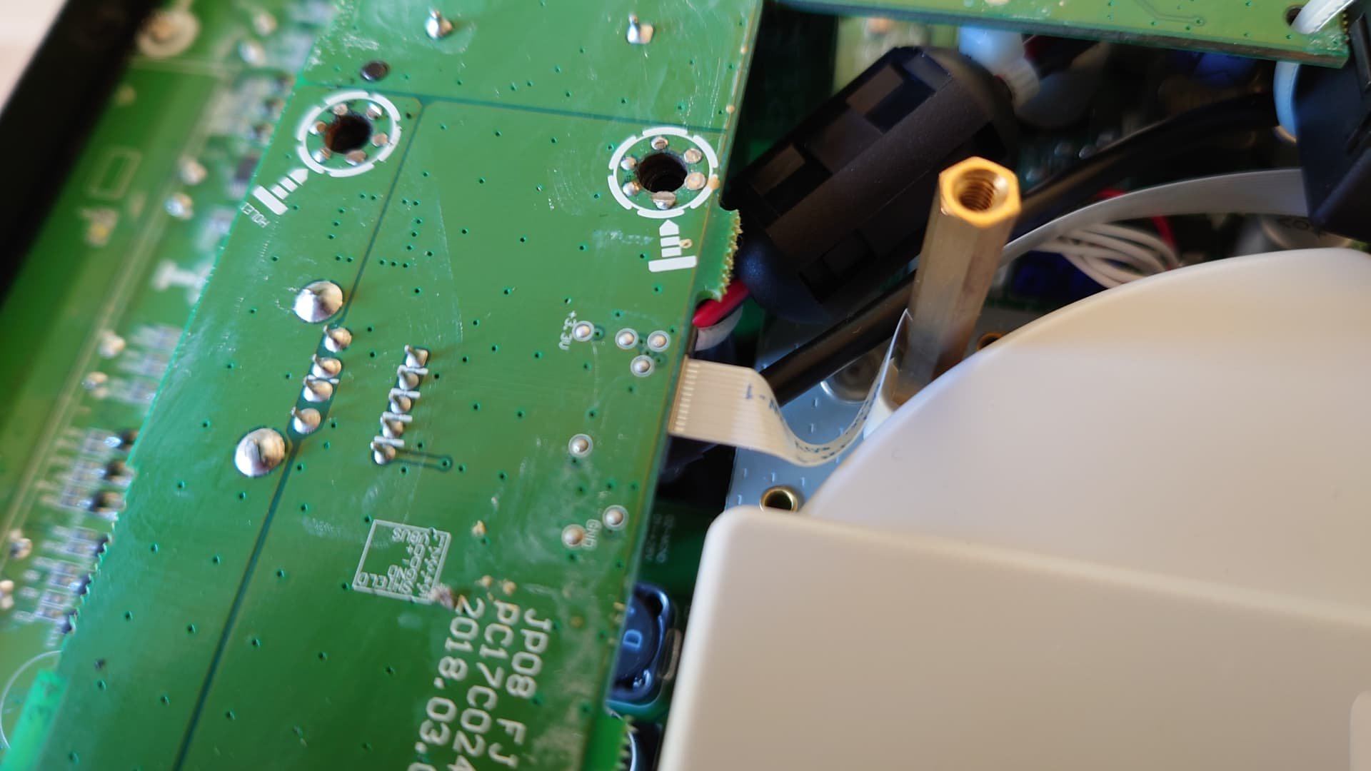
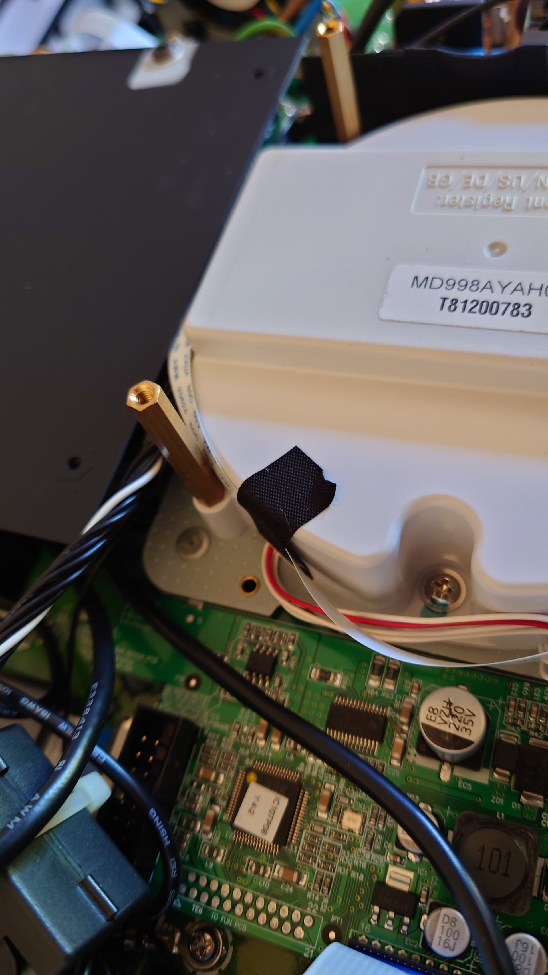
STEP 4
Detach the small flat cable, and remove the black tape that holds it attached to the motor.
STEP 4.2
STEP 4.3
You will be able to gently fold the pcb back and get it out of the way without removing any other cables. Take your time to check that nothing is in the way.
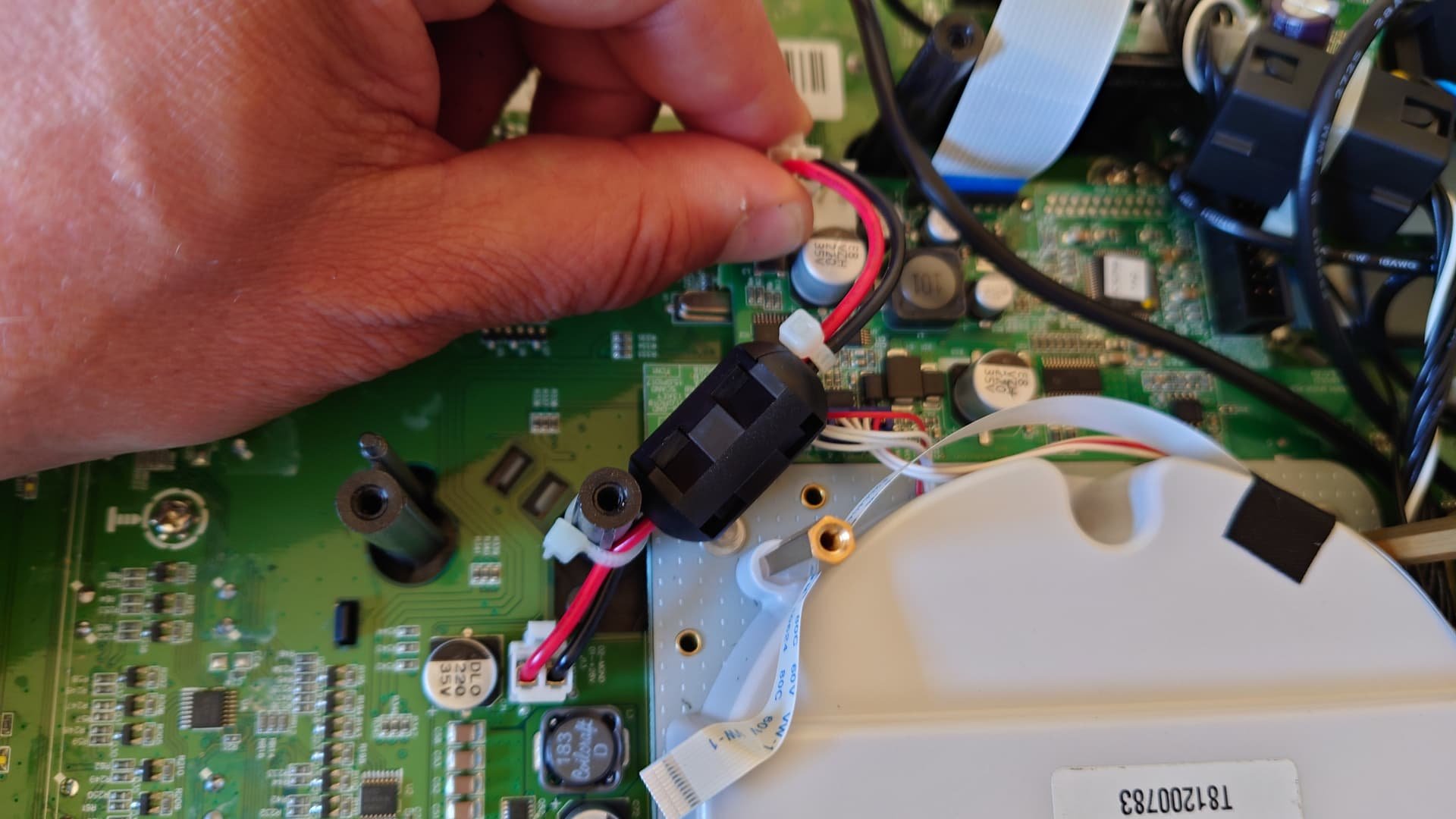
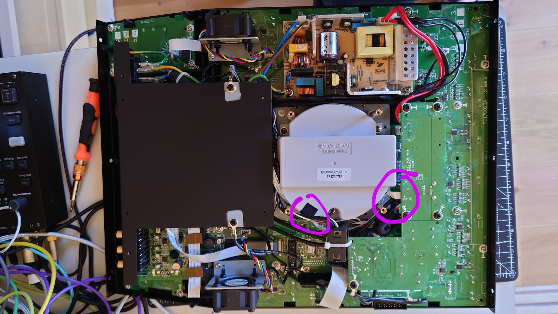
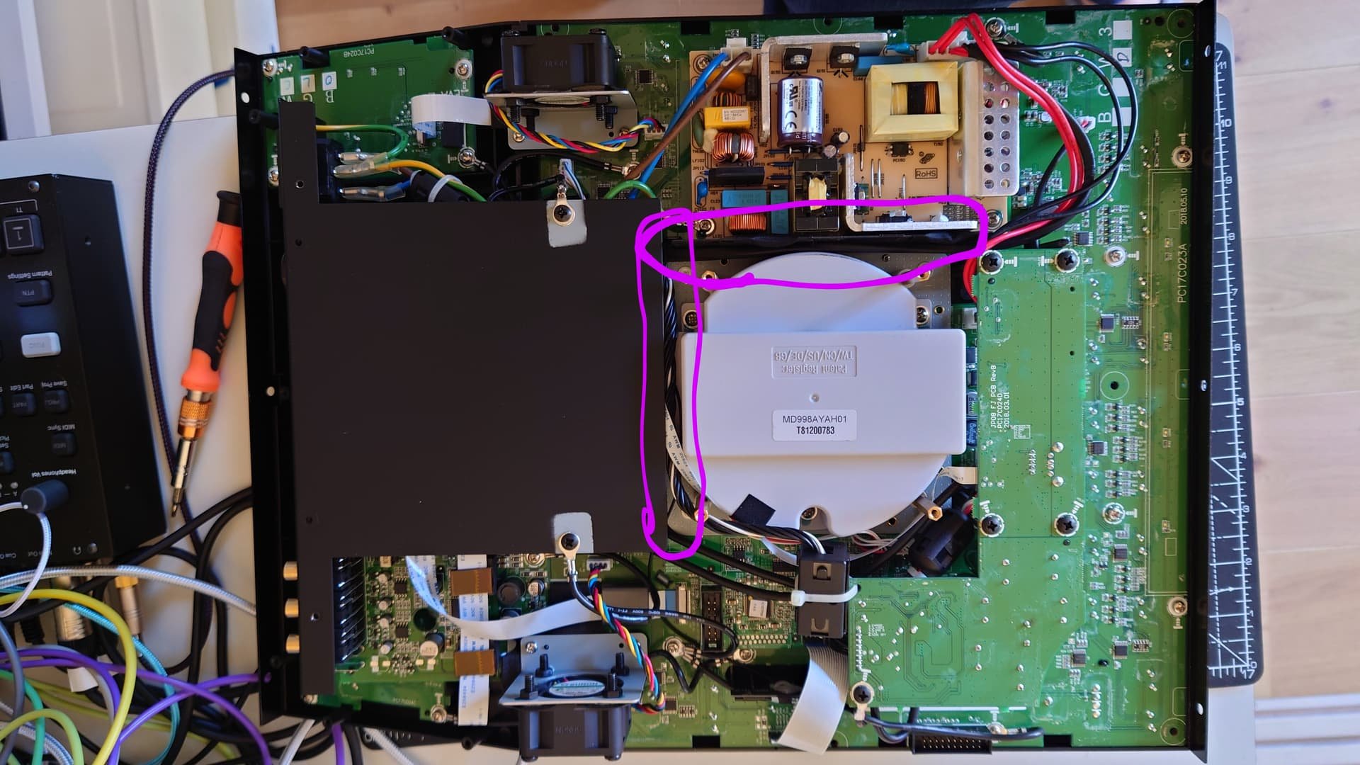
STEP 5
Remove the electric connectors at the bottom of the motor
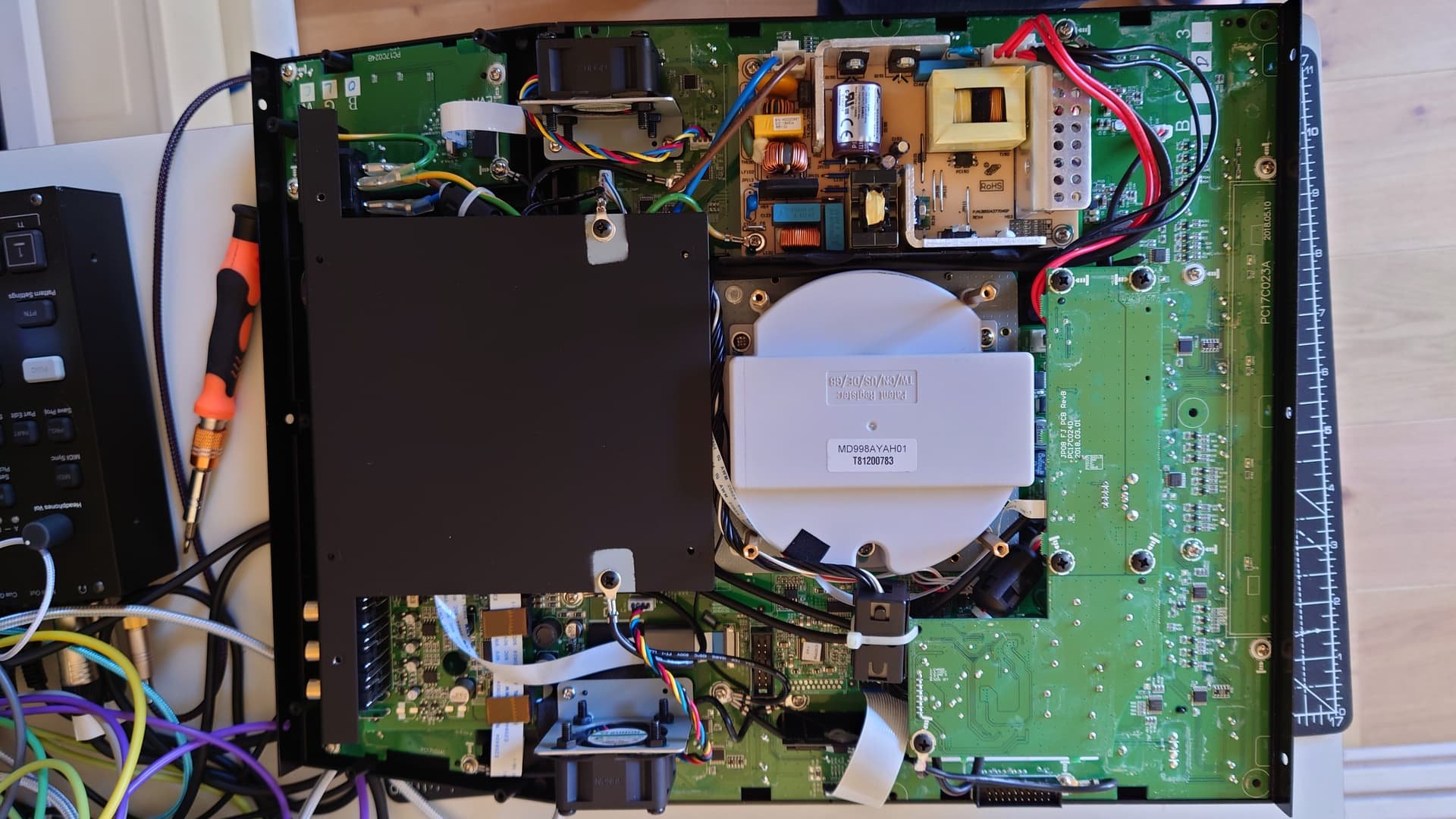
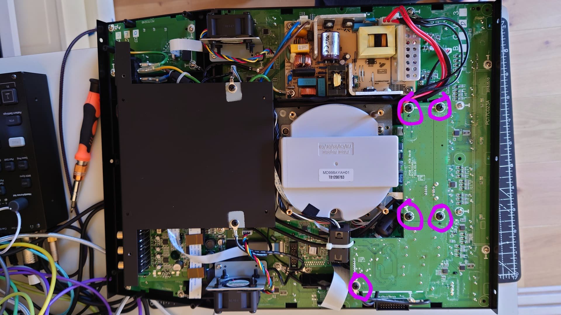
STEP 7
Carefully turn the player sideways (stuff may fall out!), or upside down if it’s easier, and remove the 4 Phillips screws that hold the motor in place.

STEP 9
Now that you have the motor out you need to take it apart. The casing is held together by 3 screws
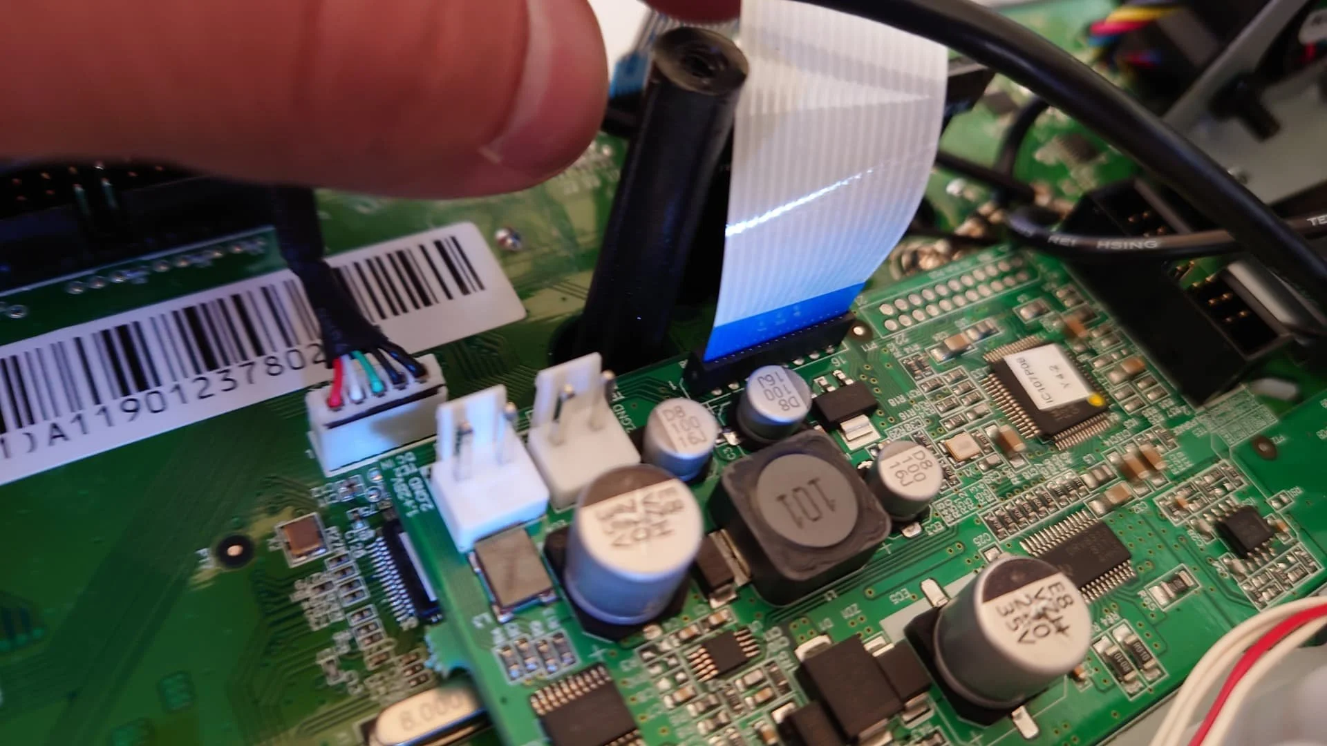
STEP 6
Also remove the nearby flat connector, so you can remove the motor block that should now be free.

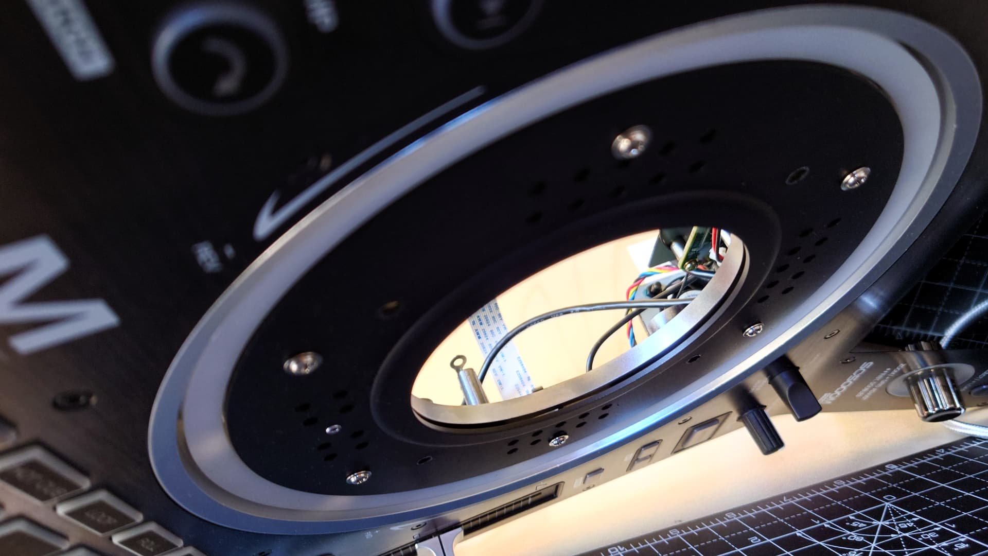
STEP 6 (OPPOSITE ANGLE)
STEP 8
Put the player on its back again and pull out the motor block. There are quite a few wires that run really close to the motor’s PCB and that need to be pushed aside to get the motor out.

STEP 8.1
Once you do that it will come out very easily. The motor is out!
Almost there - you’re doing great.

STEP 10
Then you need to remove the retaining bridge with the first encoder (2 screws).
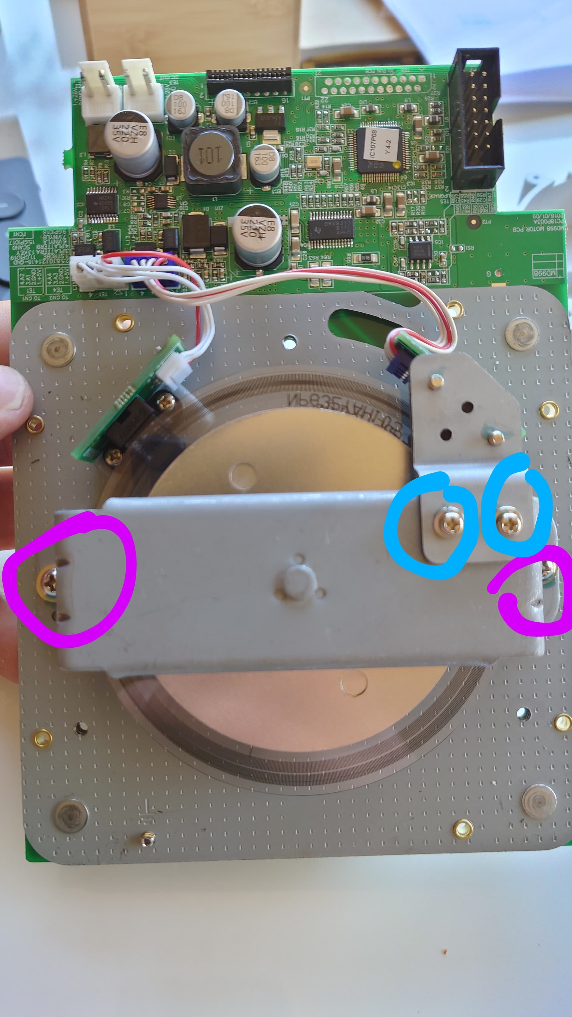
STEP 10.2
If you want to work more comfortably you can easily remove the encoder itself (2 screws, marked in blue), or you can leave it in place and just fold it back, whatever you prefer.

STEP 11
Now remove the 2 screws holding the second encoder in place

STEP 12
And using the 1.5 Allen key remove the tiny grub-screw that holds in place the top rotary disc (at the bottom in the picture. It’s the silver one, not the brass one). [PLEASE NOTE THAT IN EARLIER UNITS THAT GRUB SCREW WAS ACTUALLY A T6 TORX. Double check yours, just to make sure.]

STEP 13
At this point you will be able to push the spindle with the rotary discs through the motor
This too had a LOT more resistance than I thought - probably because of the old grease. A bit of gentle, persuasive push and pull work did the job…
You have now finished the dismantling stage.

STEP 14
Using a cotton bud or something similar remove all the old grease from the spindle and from the motor. Mine came out black .

STEP 15
Apply the new grease onto spindle and everywhere there are mechanical parts rubbing onto each other

STEP 15.2

STEP 15.3
Now carefully put everything back together following the same steps the other way round. Refer to the pictures and to the instructions to make sure you don’t miss anything. I hope my explanations were clear, but please ask me any questions you may have. You can reach me on the Engine DJ Community forum
Oh, and don’t forget to have your beers - you deserved it! And if you think I deserve a drink too for my hard work, feel free to buy me a coffee